
Datoteka:Opamptransistorlevelcolored.png
Opamptransistorlevelcolored.png (618 × 488 piksela, veličina datoteke: 10 KB, MIME tip: image/png)
| Ova je datoteka sa Zajedničkog poslužitelja i mogu je rabiti drugi projekti. Opis s njezine stranice s opisom datoteke prikazan je ispod. |
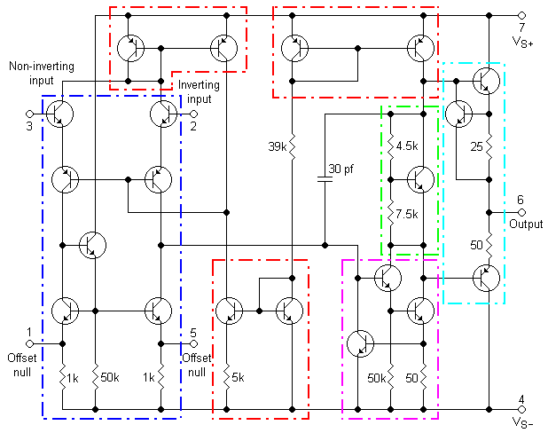
Transistor-level schematic for a 741 op-amp, color coded.
Sažetak
(See w: Op-amp#Internal_circuitry_of_741_type_op-amp for the most recent description.)
From the diagram, the blue section is a differential amplifier. The base current of the inputs is not really zero, giving the 741 an input impedance of about 2 MΩ.
The sections in red are current mirrors. The input amplifier drives a current mirror load. The top left current mirror allows large common-mode voltages on the inputs without exceeding the active range of any transistor in the circuit. The top right current mirror provides a constant current load for the output circuitry, regardless of the output voltage . The lower current mirror has a very low collector current, because of the 5 kΩ resistor. It is used as a high-impedance connection to the negative power supply, to provide a reference without loading the input circuitry.
The offset null pins are used to remove any offset voltage that would exist at the output of the op-amp when zero signal is applied to the inputs.
The high voltage gain stage is NPN.
The green section is a voltage level shifter. It provides a constant voltage drop between the top and the bottom regardless of supply voltage. If the base current to the transistor is zero, and the voltage between base and emitter (and across the 7.5 kΩ resistor) is 0.625 V (a typical value for a BJT), then the current flowing through the 4.5 kΩ resistor will be the same, and will produce a voltage of 0.375 V. This keeps the voltage across the transistor, and the two resistors at 0.625 + 0.375 = 1 V. This serves as a bias for the two output transistors, to prevent crossover distortion. In some amps this function is achieved with diodes.
The capacitor is used as part of a low pass filter (on the base of an emitter follower) to reduce the frequency response of the amp to prevent oscillations. This technique is called Miller Compensation and functions as an internal capacitive feedback.
The output in cyan is a push-pull emitter follower amplifier. It is driven by a PNP emitter-follower. The output range of the amplifier is about 1 volt less than the supply voltage, since the collector-emitter voltage of the output transistors can never go completely to zero. The resistors in the output mean that the current provided by the output is limited (about 25 mA for the 741), and the output resistance is not zero without feedback. With negative feedback it approaches zero. The output stage has current limiting circuitry.
- Opis wyprowadzeń (cyfry oznaczają numery wyprowadzeń w standardowej obudowie ośmiokońcówkowej, końcówka nr 8 - nieużywana)
- Offset null - balans zera
- Inverting input - wejście odwracające
- Non-inverting input - wejście nieodwracające
- Vs- - minus zasilania
- Offset null - balans zera
- Output - wyjście
- Vs+ - plus zasilania
Op-amp transistor level
-
 Transistor level diagram of an op-amp
 -
 Sectioned transistor level diagram of an op-amp
 -
 Sectioned transistor level diagram of an op-amp with labeled transistors


Created by User:Omegatron using Klunky schematic editor, which the creator considers public domain (possibly with post-editing in the GIMP or Inkscape)
- Slobodno smijete:
- dijeliti – umnožavati, distribuirati i javnosti priopćavati djelo
- remiksirati – prerađivati djelo
- Pod sljedećim uvjetima:
- imenovanje autora – Morate pripisati odgovarajuće autorske zasluge, dati poveznicu na licenciju, te naznačiti jesu li načinjene promjene autorskog djela. Prethodno navedeno možete učiniti na svaki razuman način, ali ne na način koji bi sugerirao da Vi ili Vaše korištenje licencorova djela ima izravno licencorovo odobrenje.
- dijeli pod istim uvjetima – Ako ovo djelo izmijenite, preoblikujete ili stvarate na osnovu tog materijala, svoje doprinose morate distribuirati pod istom ili kompatibilnom licencijom kao što je i licencija originala.

|
Dozvoljava se umnožavanje, dijeljenje i/ili mijenjanje ovog dokumenta pod uvjetima GNU-ove licence za slobodnu dokumentaciju, inačica 1.2 ili kasnija ako ju je objavio Free Software Foundation; bez nepromjenjivih ili obveznih dijelova i bez teksta na naslovnoj i/ili posljednjoj stranici. Kopija licencije je uključena u odjeljak naslovljen GNU-ove licence za slobodnu dokumentaciju. |
(In short, this means that you can copy and modify the image freely as long as you provide attribution; preferably in the form of a link back to this page.)

|
Dostupna je vektorska inačica (SVG) ove slike. Trebala bi se koristiti umjesto ove rasterske slike.
File:Opamptransistorlevelcolored.png → File:OpAmpTransistorLevel Colored.svg
Za više informacija o vektorskoj grafici, pročitajte o prelasku Zajedničkog poslužitelja na SVG. Također pročitajte informacije o podršci MediaWiki softvera slikama u SVG formatu. |
 |
Povijest datoteke
Kliknite na datum/vrijeme kako biste vidjeli datoteku kakva je tada bila.
| Datum/Vrijeme | Minijatura | Dimenzije | Suradnik | Komentar | |
|---|---|---|---|---|---|
| sadašnja | 21:36, 26. lipnja 2005. | | 618 × 488 (10 KB) | Omegatron | An electrical diagram created by User:Omegatron. (Uploaded with Wikimedia Commonplace.) Source: Created by User:Omegatron {{GFDL}}{{cc-by-sa-2.0}} Category:Electrical diagrams\ |
| 21:29, 26. lipnja 2005. |  | 618 × 488 (10 KB) | Omegatron | An electrical diagram created by User:Omegatron. (Uploaded with Wikimedia Commonplace.) Source: Created by User:Omegatron {{GFDL}}{{cc-by-sa-2.0}} Category:Electrical diagrams\ | |
| 01:50, 20. svibnja 2005. |  | 618 × 488 (10 KB) | Julo | Operation amplifier 741 {{PD}} from en:wiki |
Uporaba datoteke
Na ovu sliku vode poveznice sa sljedećih stranica:
Globalna uporaba datoteke
Sljedeći wikiji rabe ovu datoteku:
- Uporaba na en.wikipedia.org
- Uporaba na pl.wikipedia.org
- Uporaba na sl.wikipedia.org