
Datoteka:Recepteur tube limaille.JPG

Veličina ovog prikaza: 600 × 599 piksela. Ostale razlučivosti: 240 × 240 piksela | 481 × 480 piksela | 947 × 946 piksela.
Vidi sliku u punoj veličini (947 × 946 piksela, veličina datoteke: 87 KB, MIME tip: image/jpeg)
| Ova je datoteka sa Zajedničkog poslužitelja i mogu je rabiti drugi projekti. Opis s njezine stranice s opisom datoteke prikazan je ispod. |
Sažetak
| Opis |
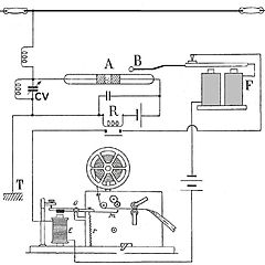
Français : Récepteur cohéreur enregistreur à tube de limaille (de Branly) 1902. Ce récepteur d'ondes hertziennes a permis de réaliser les premières liaisons radios à grande distance en radiotélégraphie. En 1902 : depuis le phare du Stiff, essais par Camille Tissot de la station Ouessant TSF avec un récepteur radio à cohéreur et un émetteur à arc à deux boules. Cette station à une portée radiotélégraphiques de 80 kilomètres avec une flotte de 14 navires en mer et avec Brest.
Français : Principe: Le tube A est en série dans-le circuit d'un élément de pile de 1,5 V et dans le circuit d'un relais sensible (généralement un relais magnétique) R. Une onde arrive, le tube devient conducteur, la palette du relais en R ce fermer un contact établissant un second circuit. Ce circuit contient: le Morse inscripteur E et un électro-aimant F, dit frappeur, cet électro-aimant mis en action attire sa palette, qui porte une sphère B, laquelle vient frapper légèrement le tube à limaille et le décohère par choc. Dès lors, revenu à son état primitif, le cohéreur est dé nouveau apte à recueillir une autre onde, qui s'inscrira à la suite de la première sur la bande du Morse.
Deutsch: RX Fritter
English: Early radio receiver circuit using a "Branly coherer", a tube containing metal filings, as a detector. This type of receiver, used until about 1906, made possible the first long distance radio telegraphy communication.
In 1902: since the headlight of Stiff, tests by Camille Tissot of the station Ushant TSF with a radio operator receiver with coherer and an arc transmitter with two balls. This station with a range radio telegraphy of 80 kilometers with a fleet of 14 ships at sea and with . The radio waves from the antenna at top are applied through a resonant circuit consisting of a coil and tuning capacitor (CV) to the coherer (A). The coherer tube is in a series circuit with a 1.5V battery and a sensitive relay (R). When a radio wave arrives, the tube becomes conducting, and the relay closes a contact in a second circuit which contains a Morse paper tape recorder (E) and an electromagnet "decoherer" or "trembler" (F). The recorder registers the signal on the tape, while the arm of the electromagnet (B) lightly taps the coherer. This disturbs the metal filings, returning the coherer to its nonconducting state so it is prepared to detect the next radio symbol. In actual operation, if the radio signal is still present when the decoherer taps the tube, the coherer immediately turns on again, causing another tap. The result is a continuous tapping or "trembling" of the electromagnet arm during the duration of each incoming Morse code symbol. |
| Datum | |
| Izvor | Vlastito djelo postavljača |
| Autor | F1jmm |
Licencija
Ja, nositelj autorskog prava za ovo djelo, ovime ga objavljujem pod sljedećim licencijama:

|
Dozvoljava se umnožavanje, dijeljenje i/ili mijenjanje ovog dokumenta pod uvjetima GNU-ove licence za slobodnu dokumentaciju, inačica 1.2 ili kasnija ako ju je objavio Free Software Foundation; bez nepromjenjivih ili obveznih dijelova i bez teksta na naslovnoj i/ili posljednjoj stranici. Kopija licencije je uključena u odjeljak naslovljen GNU-ove licence za slobodnu dokumentaciju. |
Ova datoteka je licencirana pod uvjetima Creative Commons Imenovanje-Dijeli pod istim uvjetima 3.0 nelokalizirane, 2.5 opće, 2.0 opće i 1.0 opće licencije.
- Slobodno smijete:
- dijeliti – umnožavati, distribuirati i javnosti priopćavati djelo
- remiksirati – prerađivati djelo
- Pod sljedećim uvjetima:
- imenovanje autora – Morate pripisati odgovarajuće autorske zasluge, dati poveznicu na licenciju, te naznačiti jesu li načinjene promjene autorskog djela. Prethodno navedeno možete učiniti na svaki razuman način, ali ne na način koji bi sugerirao da Vi ili Vaše korištenje licencorova djela ima izravno licencorovo odobrenje.
- dijeli pod istim uvjetima – Ako ovo djelo izmijenite, preoblikujete ili stvarate na osnovu tog materijala, svoje doprinose morate distribuirati pod istom ili kompatibilnom licencijom kao što je i licencija originala.
Možete odabrati licenciju prema vašem izboru.

|
This circuit image could be re-created using vector graphics as an SVG file. This has several advantages; see Commons:Media for cleanup for more information. If an SVG form of this image is available, please upload it and afterwards replace this template with
{{vector version available|new image name}}.
It is recommended to name the SVG file “Recepteur tube limaille.svg”—then the template Vector version available (or Vva) does not need the new image name parameter. |


Povijest datoteke
Kliknite na datum/vrijeme kako biste vidjeli datoteku kakva je tada bila.
| Datum/Vrijeme | Minijatura | Dimenzije | Suradnik | Komentar | |
|---|---|---|---|---|---|
| sadašnja | 07:15, 30. srpnja 2010. | | 947 × 946 (87 KB) | F1jmm | ffu phare |
| 17:22, 15. rujna 2009. |  | 947 × 946 (99 KB) | F1jmm | faible impédance | |
| 16:40, 14. ožujka 2009. |  | 986 × 954 (105 KB) | F1jmm | {{Information |Description= {{fr| Récepteur cohéreur enregistreur à tube de limaille (de Branly) 1902 }} |Source=travail personnel (own work) |Date=15 Mars 2009 |Author=F1jmm |Permission= |other_versions=1 }} <!--{{ImageUpload|basic}}-- |
Uporaba datoteke
Na ovu sliku vode poveznice sa sljedećih stranica:
Globalna uporaba datoteke
Sljedeći wikiji rabe ovu datoteku:
- Uporaba na en.wikipedia.org
- Uporaba na eo.wikipedia.org
- Uporaba na fr.wikipedia.org
- Uporaba na pl.wikipedia.org